Introduction
Flooded evaporators live or die by liquid level control. Get it wrong, and you're either flooding the compressor with liquid or starving the coil of refrigerant.
Low-side float valves are the mechanical workhorses that keep that level steady, using nothing more than buoyancy and a needle-and-seat assembly.
Many engineers and technicians mix up low-side and high-side float valves, or underestimate how much float material and construction quality affect long-term reliability. That confusion leads to premature failures, inconsistent liquid levels, and costly downtime.
This guide breaks down how low-side float valves actually work, how they differ from high-side designs, where they show up beyond refrigeration, and how to select the right float components for your system.
Key Takeaways
- Low-side float valves control liquid refrigerant level directly in the evaporator at suction-side pressure
- Low-side valves must handle the full high-to-low pressure differential, unlike high-side designs
- Common uses include ammonia refrigeration, ice-making, wastewater treatment, steam traps, and sump systems
- Float material, especially stainless steel grade, sets pressure tolerance and service life
What Is a Low-Side Float Valve?
A low-side float valve is a mechanical, self-regulating expansion device that maintains liquid level directly inside the evaporator or an attached surge drum. It operates at evaporating (suction-side) pressure rather than condensing pressure.
Manufacturer literature from Phillips describes its Series 300H low-side valves as fixed-level, modulating liquid-level controls built primarily for ammonia (R-717) systems, typically mounted on a vertical or horizontal surge drum serving a single evaporator.
That setup matches ASHRAE's definition of a flooded evaporator: most of the coil surface stays in contact with liquid refrigerant, with no organized refrigerant flow pattern.
How a Low-Side Float Valve Works
The operating logic is simple:
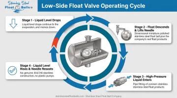
- Liquid level drops as refrigerant evaporates and pulls vapor toward the compressor
- The float descends, and through a cam, lever, or direct linkage, lifts the needle off its seat
- High-pressure liquid enters from the receiver or liquid line, replenishing the surge drum
- Liquid level rises, the float follows, and the needle reseats to stop flow
Unlike a high-side float, which regulates liquid leaving a high-pressure receiver, a low-side valve admits liquid straight from the high side into the evaporator. It must handle the full pressure differential between the receiver and the evaporator, not just modulate flow within one pressure zone.
Parker's pressure-temperature chart lists R-717 saturation pressure at 33 psig at 20°F and 155 psig at 86°F. Under those conditions, a low-side float valve could see a differential of roughly 122 psid. That figure is a calculated example, not a fixed industry number, but it shows why these valves need durable seat and needle construction.
Larger systems sometimes use pilot-operated low-side float valves. Here, the float assembly acts as a pilot for a bigger liquid-line or pilot-operated valve, giving the system more flow capacity without needing an oversized, sluggish float mechanism.
Key Components of a Low-Side Float Valve
Every low-side float valve relies on the same core parts:
- Float element: often stainless steel for corrosion resistance and dimensional stability under pressure
- Valve body: rated for the full high-to-low pressure differential, not just line pressure
- Needle and seat: precision-machined to seal tightly against high-pressure liquid feed
- Mechanical linkage: cam, lever, or pusher rod connecting float movement to needle position
Float material choice directly affects buoyancy consistency. A float that corrodes, pits, or absorbs liquid over time loses its predictable buoyancy curve, and level control starts drifting.
Low-Side vs. High-Side Float Valves: Key Differences
The high side of a refrigeration system runs between the compressor discharge and the expansion device, at condensing pressure. The low side runs between the expansion device and the compressor inlet, at evaporating pressure. That distinction is the entire basis for how the two float valve types differ.
High-side float valves sit in the liquid line between the condenser and evaporator. Low-side float valves are integrated directly into the evaporator or its surge drum.
| Factor | Low-Side Float Valve | High-Side Float Valve |
|---|---|---|
| Location controlled | Evaporator or surge drum | Condenser/receiver liquid line |
| Response to rising level | Closes to reduce feed | Opens to release excess liquid |
| Operating pressure (R-717 example) | ~16–33 psig (0–20°F) | ~155–180 psig (86–95°F) |
| Pressure differential handled | High, since it meters from high-side liquid | Low, since it only handles low-pressure liquid |
| Best application fit | Single flooded evaporator needing constant level | Multiple evaporators with varying loads |
Danfoss specifies its SV 4-6 low-pressure float valves for flooded evaporators where only slight liquid-level variations are acceptable. Maximum differentials range from 19 to 23 bar (about 275–335 psig) depending on model.
That tighter control is why low-side valves get chosen for ammonia systems and ice-making equipment. They hold a more consistent level than a high-side design managing multiple loads downstream.
Installation orientation also matters more for low-side valves. The float sits inside a pressurized vessel exposed to incoming liquid, so it needs baffle shielding and room to move freely. That requirement is less critical for high-side floats in a simpler liquid-line chamber.
Where Low-Side Float Valves Are Used
Low-side float valves are most common in ammonia (R-717) refrigeration systems, where precise level control in flooded evaporators is critical for both efficiency and compressor protection. Typical settings include:
- Flooded shell-and-tube and surge-drum evaporators
- Ice-making equipment and ice-cream freezing units
- Large cold storage and industrial chiller plants
The same buoyancy-and-valve principle applies outside refrigeration. Anywhere a system must respond automatically to a changing liquid level, a float mechanism fits:
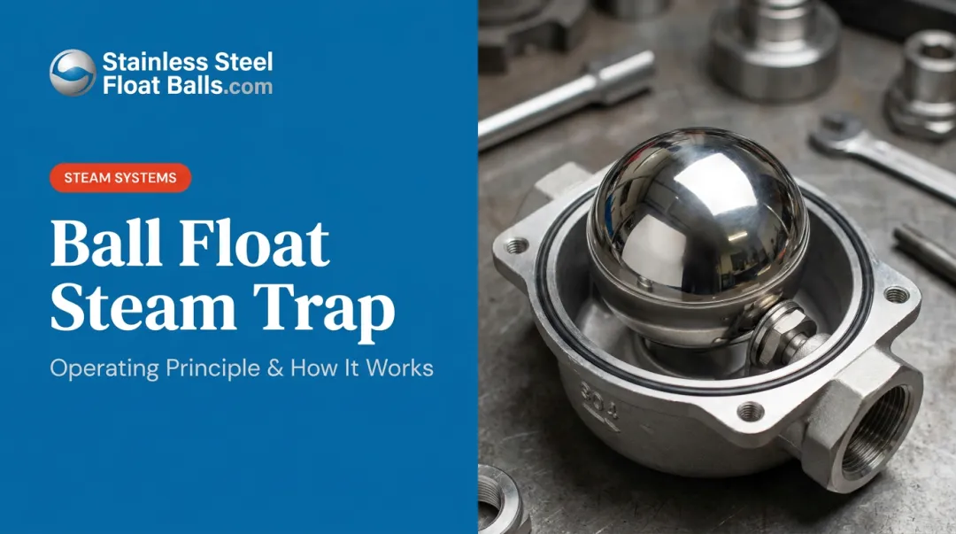
- Steam traps: rising condensate lifts a ball float and opens a valve to release condensate
- Sump pumps: float switches start or stop the pump at set high or low levels
- Wastewater treatment: float sensors monitor levels in treatment and holding tanks
- Chemical manufacturing: floats track levels in storage and process tanks, including corrosive service
Float mechanisms also appear in niche uses such as vacuum tank shutoff systems and level measurement with floats on guide rods or cables. Across every case, buoyancy drives mechanical action directly—no electronic sensors or external power required.
Choosing the Right Float & Materials for Low-Side Valve Systems
Float selection is not an afterthought. It determines whether your valve holds up under real operating conditions. Low-side applications combine two tough factors: high pressure differentials and, often, corrosive media like ammonia or food-grade liquids.
Material matters here. OSHA's regulation on anhydrous ammonia storage, 29 CFR 1910.111, prohibits brass, copper, and galvanized-steel piping in the ammonia systems it covers. Those materials can be attacked by ammonia over time. Stainless steel, typically 304 or 316 grade, is the standard alternative for float elements exposed to ammonia or other aggressive liquids.
- 304 stainless steel covers most standard applications: liquid level measurement, float valves, sump pumps, and food processing involving oils or syrups
- 316 stainless steel adds resistance to chlorides and harsher chemicals, making it the better fit for chemical manufacturing and wastewater treatment
Sizing, Shape, and Fitting Considerations
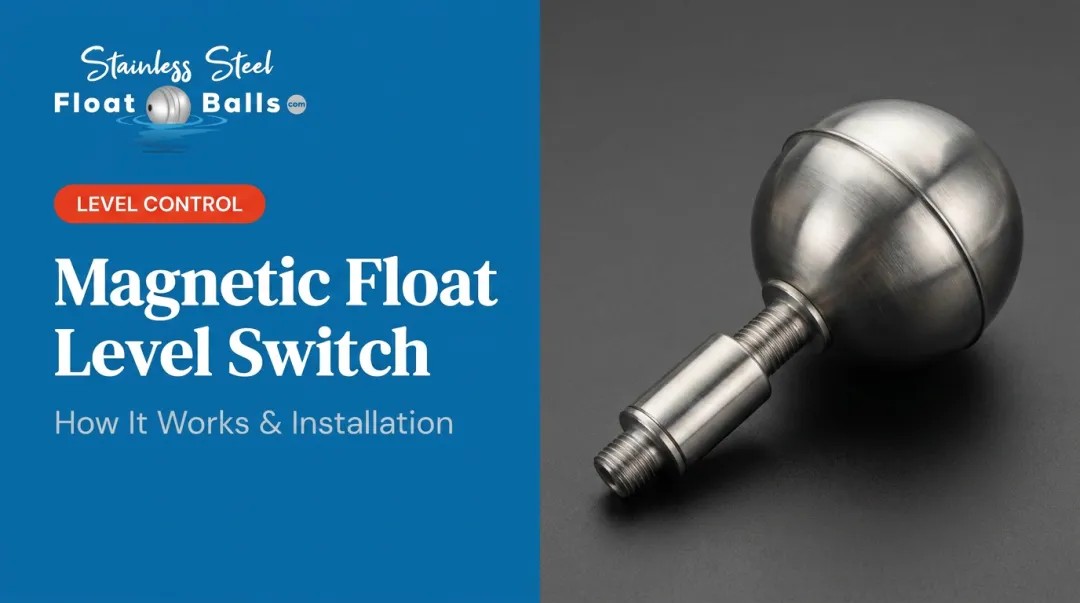
Floats also need to match the physical geometry of the valve assembly, not just the chemistry of the system. Round floats and oblong (oval) floats serve different mounting configurations, and many designs require custom threading, through-tubes for rod mounting, or embedded magnets for non-contact level sensing.
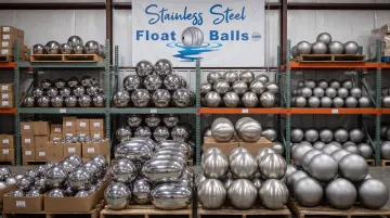
Float valve manufacturers and system integrators often need a supplier that already stocks those configurations. Stainless Steel Float Ball Company maintains a large ready-to-ship inventory built for that use case:
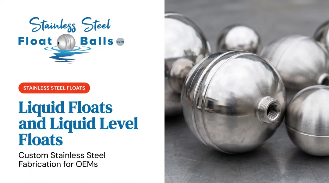
- Round floats from 1-1/2" to 14" in diameter
- Oblong configurations from 2×6" up to 9×14"
- 304SS or 316SS construction
- Custom threading (NPT or UNC), through-tubes for rod-guided applications, and internal magnets on standard or custom sizes
Every float is pressure-tested to the customer's specific system requirements rather than a generic standard. That matters when a low-side float valve has to tolerate high differential pressure.
With over 20 years manufacturing stainless steel floats and direct worldwide shipping from the factory, sizes not currently in stock can typically be added to inventory rather than handled as one-off specials. Requests can go through the contact page or directly by phone or email.
Finish choice matters too, particularly for sanitary or corrosion-sensitive settings:
- Matte (unfinished) — standard finish, visible weld ring, fine for general industrial use
- Brushed — smoothed weld seam, cleaner appearance without full mirror cost
- Polished (mirror) — highest hygiene standard, easiest to clean, preferred in food processing tanks handling oils and syrups
Installation, Maintenance & Troubleshooting Tips
Correct installation starts with free, unobstructed float travel. Keep the float area clear, and add a baffle so incoming liquid does not hit the float directly—it should track actual tank level, not turbulence. Manufacturer guidance also recommends:
- Install an upstream strainer or liquid-line filter to keep debris off the needle and seat
- Add an isolation valve ahead of the float assembly so you can service it without draining the system
- Include a hand-expansion bypass to keep feeding the evaporator during float valve service
Common Problems and Fixes
| Symptom | Likely Cause | Corrective Action |
|---|---|---|
| Liquid level hunting or swinging | Excessive flash gas, balance-pipe pressure drop | Consider external or direct expansion into the surge drum |
| Vessel overfeeding (flooding) | Worn cartridge, jammed pusher, or leaking float | Inspect and replace cartridge or float element |
| Evaporator starvation | Pusher stuck, preventing cartridge from opening | Clear obstruction or replace linkage |
A basic maintenance routine catches most of these issues early:
- Visually check the sight glass periodically for level consistency
- Inspect the float for leaks — a float that's taken on liquid loses buoyancy accuracy
- Check linkage for wear or corrosion, especially on systems running ammonia or other aggressive media
Frequently Asked Questions
What is a low-side float valve?
A low-side float valve is a float-operated expansion device that maintains liquid refrigerant level directly in the evaporator at suction (evaporating) pressure. It admits high-pressure liquid as the level drops and shuts off as the level rises.
What is the difference between the high side and low side of a refrigeration system?
The high side runs between the compressor discharge and the expansion device at condensing pressure. The low side runs between the expansion device and the compressor inlet at evaporating pressure.
How do you know if a float valve is malfunctioning?
Watch for erratic or hunting liquid levels, signs of compressor flooding, or evaporator starvation. These usually point to a worn cartridge, stuck pusher, or leaking float.
What materials are low-side float valves typically made from?
Stainless steel, usually 304 or 316 grade, is the standard choice for float elements and valve bodies. It resists corrosion far better than copper or brass, which ammonia can attack over time.
Can float valve mechanisms be used outside of refrigeration systems?
Yes. The same buoyancy principle drives float switches in sump pumps, steam traps, wastewater treatment tanks, and various liquid-level control systems.
What causes a float valve to get stuck?
Debris accumulation, corrosion on the float or linkage, and general mechanical wear are the most common causes. Regular inspection of the linkage and float surface helps catch problems early.