Introduction
Picture a storage tank pump running dry at 2 a.m. — no operator present, no alarm triggered, bearings and shaft seals quietly grinding to failure. Or the opposite: a tank overflowing because the fill line never got the signal to stop. According to the CSB's investigation of the 2009 CAPECO incident, a gasoline tank overfill produced a 107-acre vapor cloud — and an independent high-level alarm could have warned operators before it escalated.
Magnetic float level switches exist to prevent exactly these failures. They've been a trusted technology in industrial liquid control for decades — mechanically simple, electrically reliable, and built to run with minimal maintenance.
This article covers:
- What a magnetic float level switch is and how it works step by step
- Key components, including the float ball at the center of the design
- Mounting types and how to choose between them
- Installation best practices
- Where these switches are used across industries
Key Takeaways
- A magnetic float level switch provides a discrete on/off signal at a fixed liquid level — not a continuous measurement
- The reed switch never contacts the liquid, eliminating electrical wear at the sensing point
- Float material, liquid density, and electrical load rating drive every selection decision
- NO vs. NC configuration determines whether the circuit activates or breaks when the float triggers
- Turbulence, current overload, and liquid incompatibility are the top causes of premature failure
What Is a Magnetic Float Level Switch?
A magnetic float level switch detects when liquid in a tank or vessel reaches a specific high or low set point, then outputs a discrete electrical signal — either open or closed — to a control system. The switching action requires no external power — it's driven entirely by magnetic force.
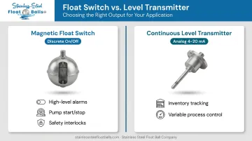
This distinguishes it from a continuous level transmitter, which outputs an analog signal (typically 4–20 mA) representing the full liquid height at any given moment. As WIKA describes it, a float switch provides point-based limit level detection — it tells you when liquid has reached a threshold, not where it is at all times.
When to use each:
| Sensor Type | Output | Best For |
|---|---|---|
| Magnetic float switch | Discrete on/off | Alarms, pump start/stop, safety interlocks |
| Continuous level transmitter | Analog (4–20 mA) | Inventory tracking, variable process control |
Float switches earn their place in industrial systems for straightforward reasons:
- No electrical contacts exposed to the process liquid
- Minimal moving parts — fewer failure points over time
- Compatible with a wide range of media, from water and light oils to corrosive chemicals
Key Components of a Magnetic Float Level Switch
The Float Ball
The float is the primary sensing element. It rides the liquid surface, rising and falling as level changes. Inside its sealed hollow body sits a permanent magnet — completely isolated from the process liquid. Buoyancy keeps the float precisely tracking the surface: the upward force equals the weight of liquid displaced, so the float responds proportionally to level changes at any fill rate.
Float material matters in demanding environments. Stainless Steel Float Ball Company manufactures custom float balls in 304SS and 316SS for exactly these conditions — available in round sizes from 1½" to 14" and oblong configurations from 2×6" to 9×14". Embedded magnets are installed to customer specifications, with pressure testing available for high-pressure or steam system applications.
The Reed Switch
Two ferromagnetic contact reeds are sealed inside a glass tube. When the float's magnet passes close enough, the magnetic field snaps the contacts open or closed. Because the float never physically touches the reed switch assembly, there is zero electrical wear at the sensing point. The switch activates through the tube wall without mechanical contact.
Reed switches respond in milliseconds: the Standex ORD213, for example, lists a 0.3 ms typical operate time. This rapid response means the switch activates cleanly at the set point regardless of fill speed.
The Stem or Guide Tube
A non-magnetic stem — typically stainless steel or engineering plastic — houses the reed switch and guides the float's travel. This barrier separates the switch mechanism from the process liquid, protecting it from corrosion, pressure, and contamination. Vertical multi-point designs use a single stem with multiple reed switches at different heights for detecting several discrete levels with one assembly.
Switch Enclosure and Electrical Output
The enclosure protects terminals and wiring from the installation environment. Ratings are selected based on conditions:
- IP65 — dust-tight, protected against water jets (IEC 60529)
- NEMA 7 — indoor hazardous classified locations
- ATEX/IECEx — explosive atmospheres per Directive 2014/34/EU
The output is a dry contact (potential-free), meaning the switch carries no voltage of its own. It comes in two configurations:
- Normally Open (NO): Contacts open at rest; close when float activates
- Normally Closed (NC): Contacts closed at rest; open when float activates
Choosing between NO and NC determines your system's fail-safe behavior: a normally closed switch keeps a pump running and cuts power on high-level detection, while a normally open switch does the opposite.
How a Magnetic Float Level Switch Works
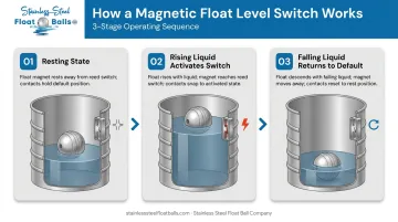
Step 1 — Resting State
At normal operating level, the float sits at a position where its embedded magnet is away from the reed switch. The switch remains in its default state — open if NO-configured, closed if NC-configured. No signal change, no action from the control system.
Step 2 — Rising Liquid Activates the Switch
As liquid rises, buoyancy lifts the float upward along the stem. When the magnet reaches the reed switch's operate field threshold, the magnetic force snaps the contacts to their activated position. The switchover is fast and decisive: the Littelfuse MARR-5 reed switch lists a maximum operate time of 0.75 ms, with no gradual transition — just a clean state change.
Step 3 — Falling Liquid Returns the Switch to Default
As liquid drops, the float descends, pulling the magnet away from the reed switch. The contacts return to their resting state. This cycle can repeat reliably for tens of millions of operations — reed switch manufacturers qualify their components to that threshold under appropriate load conditions.
What the Control System Receives
Once the contacts change state, that dry contact output connects to a PLC input, relay, or control panel. From there, the control logic determines what happens next:
- Start or stop a pump
- Open or close a valve
- Trigger an alarm
- Log the event to a SCADA or data system
The float switch reports the level state. Everything else is programmed externally.
One important caveat: never switch pump motor current directly through a reed contact. Reed switches are low-power devices. An interposing relay or PLC input module must handle motor loads.
Types of Magnetic Float Level Switches
Horizontal vs. Vertical Mounting
Horizontal (side-mount) switches install through the tank wall and pivot up or down as liquid rises or falls. The pivot mechanism actuates the reed switch at the set level. These suit installations where top or bottom tank access isn't available, and they work well for single-point detection on storage vessels.
Vertical switches mount from the top or bottom of the tank, with the float sliding along a stem. They're better suited for:
- Narrow tanks where a side-pivoting arm would be obstructed
- Multi-point detection (multiple reed switches along one stem)
- Applications requiring a guided float path for accuracy
The Madison M Series multi-point design, for example, places multiple reed switches at defined positions along a single vertical stem, allowing one assembly to cover several discrete level alarms or pump-control points.
Once you've determined the mounting orientation, the next decision is circuit behavior.
Normally Open (NO) vs. Normally Closed (NC)
Your circuit behavior requirement determines which to specify:
- NO switches activate the circuit when liquid reaches the float — used for high-level alarms, overflow prevention, or starting a fill pump
- NC switches keep the circuit active during normal operation and break it when the float triggers — used for low-level shutoffs, pump dry-run protection, and safety interlocks where a de-energized state signals a fault
How to Install a Magnetic Float Level Switch
Pre-Installation Checks
Before mounting anything, verify:
- Confirm wetted part material against process fluid — 316SS is required for corrosive media, food-grade liquids, and elevated temperatures
- Check pressure and temperature ratings on the product datasheet directly — ratings vary significantly between models
- Verify the NO/NC output configuration matches your control system logic, and that reed contact voltage and current ratings are not exceeded
Mounting the Switch
Vertical installation:
- Insert the stem through the tank's top port
- Secure with the threaded fitting or flange to the specified immersion depth
- Confirm the reed switch position on the stem aligns with the target level set point
- Torque the fitting to manufacturer specification — a leak-free seal depends on it
Horizontal installation:
- Mount the switch body through the tank sidewall at the target level
- Confirm the float arm has full range of motion inside the tank — no baffles, pipes, or fittings blocking the pivot arc
- Verify the float hangs freely in the liquid without resting against the tank wall
Wiring the Switch
Connect the two output leads to the control panel or relay input per the wiring diagram. Key rules:
- Confirm circuit voltage does not exceed the switch's rated load
- Route wiring through conduit rated for the environment (explosion-proof conduit for classified areas)
- Use an interposing relay if switching any inductive load — motor starters, solenoids, or contactors
Testing Before Commissioning
Test before introducing any process fluid to catch wiring errors and confirm set point accuracy:
- Dry magnet test: Hold a magnet near the reed switch location on the stem to simulate float activation. Verify the control panel, pump, or alarm responds correctly before the tank contains any liquid.
- Wet fill test: Slowly fill the tank while monitoring the set point. Confirm the switch triggers at the intended level and that the control response is correct.
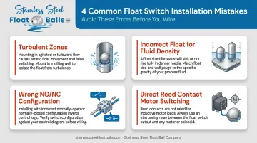
Common Installation Mistakes to Avoid
- Avoid turbulent zones — agitation and slosh cause false triggering. Mount in a stilling well or baffled location instead.
- Account for liquid specific gravity — lighter fluids generate less buoyancy force. A float sized for water may not ride correctly in a light hydrocarbon, so match float size to media density.
- Confirm NO/NC configuration before wiring — installing a normally-open switch where a normally-closed is required inverts the control logic entirely.
- Never switch pump current directly through the reed contact — this is the most common cause of premature electrical failure. Always use an interposing relay for inductive loads.
Common Applications Across Industries
Water, wastewater, and industrial storage: Float switches control pumps in sump systems, lift stations, and storage tanks — starting fill pumps at low level, stopping them at high level, or triggering overflow alarms. EPA 40 CFR Part 280 requires underground storage tank overfill equipment to alert operators at no more than 90% full, or shut off flow at no more than 95% full — a regulatory driver for independent point-level alarm inputs.
Food processing and chemical manufacturing: The non-contact magnetic design keeps electrical components out of the process stream entirely. Stainless steel wetted parts — float ball and stem — meet corrosion-resistance requirements for acids, solvents, syrups, and oils.
Stainless Steel Float Ball Company supplies 304SS and 316SS float balls for OEM integration into food and chemical processing equipment. Key options include:
- Food-safe finishes (brushed or fully polished mirror)
- Custom threading in NPT and UNC standards
- Through-tube configurations for drop-in assembly
Boilers, steam systems, and high-pressure vessels: Gems Warrick float level switches, for instance, include low-level pump control specifically designed for boiler systems, using redundant reed switches for added reliability. In these environments, the absence of mechanical wear in the sensing mechanism is a clear advantage — spring-loaded or pivot-based designs degrade under thermal cycling, while the sealed reed/magnet arrangement does not. Stainless Steel Float Ball Company's pressure-tested float balls with embedded magnets are available for these demanding conditions, tested to customer specifications.
Frequently Asked Questions
How do magnetic float switches work?
A permanent magnet sealed inside a float rides the liquid surface. When the liquid rises or falls enough to bring the magnet near a sealed reed switch in the stem, the magnetic field snaps the reed contacts open or closed. That state change sends a dry contact signal to a pump, alarm, or PLC.
What is the difference between a normally open and normally closed float switch?
A normally open (NO) switch has contacts open at rest and closes when the float activates. A normally closed (NC) switch has contacts closed at rest and opens when the float activates. The right choice depends on whether your control system needs to energize or de-energize when the level is reached.
Can magnetic float level switches be used with corrosive or viscous liquids?
316SS float balls and stems handle most corrosive media well. For viscous liquids, a larger float may be needed to generate sufficient buoyancy — but the reed switch mechanism itself is unaffected by viscosity since activation is magnetic, with no physical contact required between float and switch.
How do you set the float switch level?
For vertical switches, position the reed switch on the stem at the correct depth during installation — that location becomes the set point. For horizontal switches, mounting height on the tank wall sets the activation level. Both are fixed once installed; changing the set point requires repositioning the switch or reed.
What causes a magnetic float level switch to fail?
The four most common failure modes are: scale or debris build-up preventing free float movement; float material incompatibility causing corrosion or cracking; reed switch failure from exceeding its electrical load rating; and false triggering or stem wear from installation in high-turbulence zones.
How long do magnetic float level switches last?
With correct material selection and proper electrical loading, these switches can deliver millions of cycles over many years. Longevity depends on float material compatibility with the process liquid and keeping reed contact loads within the rated specification — exceeding that rating shortens reed life sharply.